

SFU SATELLITE DESIGN TEAM

An ALEASAT work session on SFU Burnaby campus
Overview

My teammates and I attaching accelerometers for vibration testing in the Canadian Space Agency's David Florida Laboratory.
I joined the SFU Satellite Design Team in September of 2017. I am currently serving as an advisor for the ALEASAT project that I was the project manager on for 2 years. My work in the past has been primarily on the ADCS (Attitude Determination & Control Systems) sub-team which I helped lead for nearly a year. Below you will find details on the past and present projects our team has worked on. These projects include ALEASAT, two iterations of the Canadian Satellite Design Challenge (CSDC), The Canadian CubeSat Project (CCP), and a High-altitude Balloon Project.
Website: www.sfusat.org
GitLab: www.gitlab.com/sfusat
Wiki: www.teamsfusat.wiki
ALEASAT

A render of the ALEASAT spacecraft
I started and lead a 70-person joint SFU and UBC CubeSat project with a planned launch in 2023. The ALEASAT project started in January 2020 as a collaborative project between the SFU Satellite Design Team and UBC Orbit. The project includes the design, assembly, integration, testing, launch, and operations of a 1U CubeSat. The satellite is, in part, derived from the SFU and UBC satellites from The Canadian Satellite Design Challenge 5 (see further down this page). The first payload is an in-house reaction wheel that I helped design which will prove the reaction wheel design in flight and serve as a scale model centrifuge to investigate the dynamics and vibrations for a future short-arm human centrifuge design being worked on at the SFU Aerospace Physiology Lab. The second payload is a camera that will take a photo of an amateur radio operator’s location and downlink the image.
I am currently acting as an advisor on the project. Previously, for 2 years, I was acting as the project manager and overseeing the ALEASAT project as a whole including managing the integration and administrative meetings and team-wide communications. Additionally, I was in charge of launch procurement and licensing of our camera and RF systems. I was coordinating directly with both university faculties, the collaborating labs (SFU Aerospace Physiology Lab and the UBC Radio Science Lab), the launch service provider, the Canadian and International licensing bodies, and our testing facilities. My primary technical work on the project was in mission design, systems engineering, attitude determination and control systems (ADCS), and the centrifuge payload. I had been working on the high-level system architecture and defining the mission timeline, budget, requirements, interfaces, test plans, and CONOPS. The work I was doing on the ADCS and centrifuge payload was carried over from my work on these systems in the previous CSDCs. The centrifuge payload will be a flight model of the reaction wheel designed by myself and the rest of the SFU ADCS team for CSDC 5.

Systems-level diagram of the centrifuge/reaction wheel payload

Systems-level diagram of the entire ALEASAT spacecraft

CONOPS diagram for the camera payload

CONOPS diagram for the centrifuge payload

ALEASAT Project Team Structure
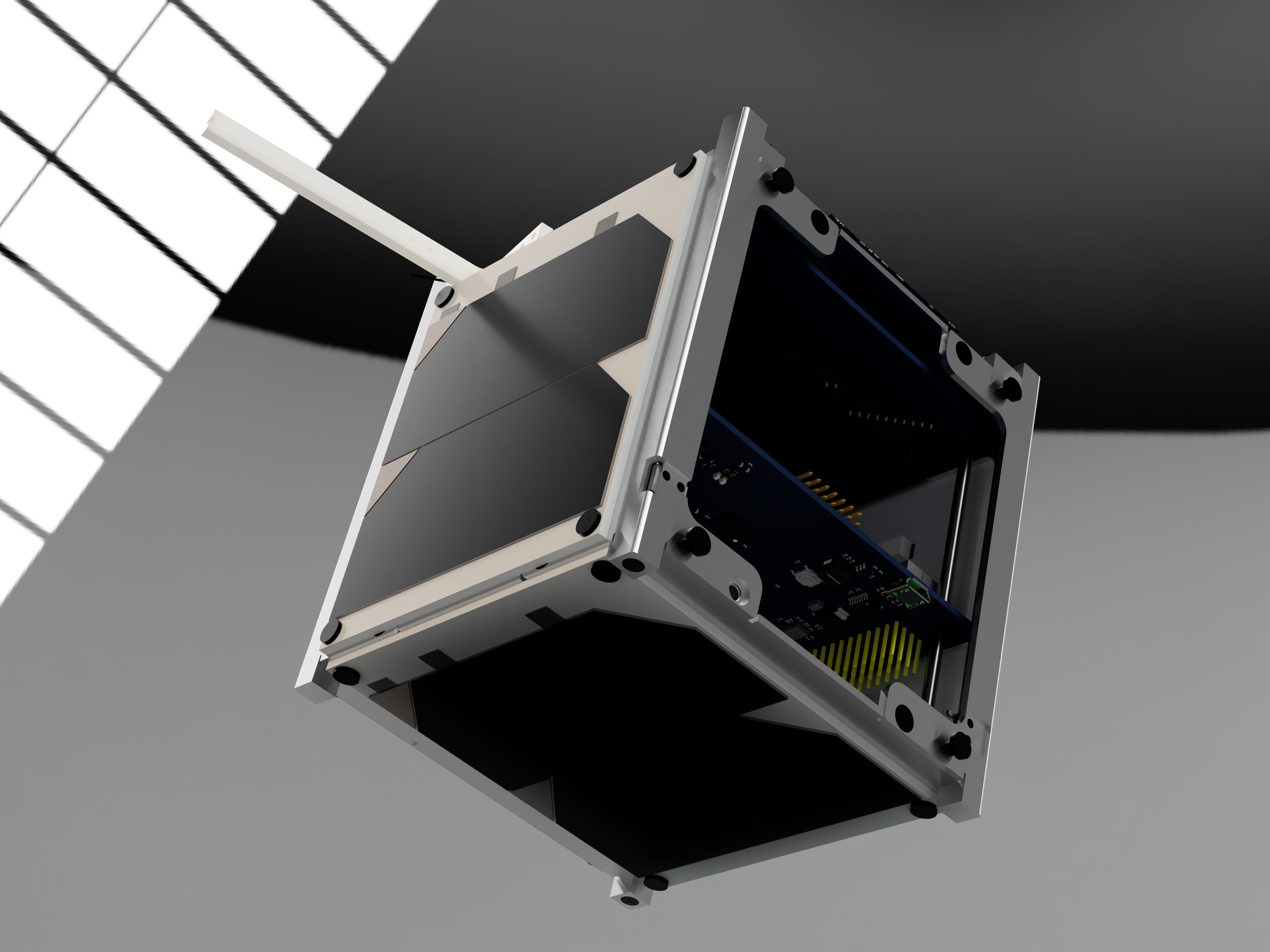
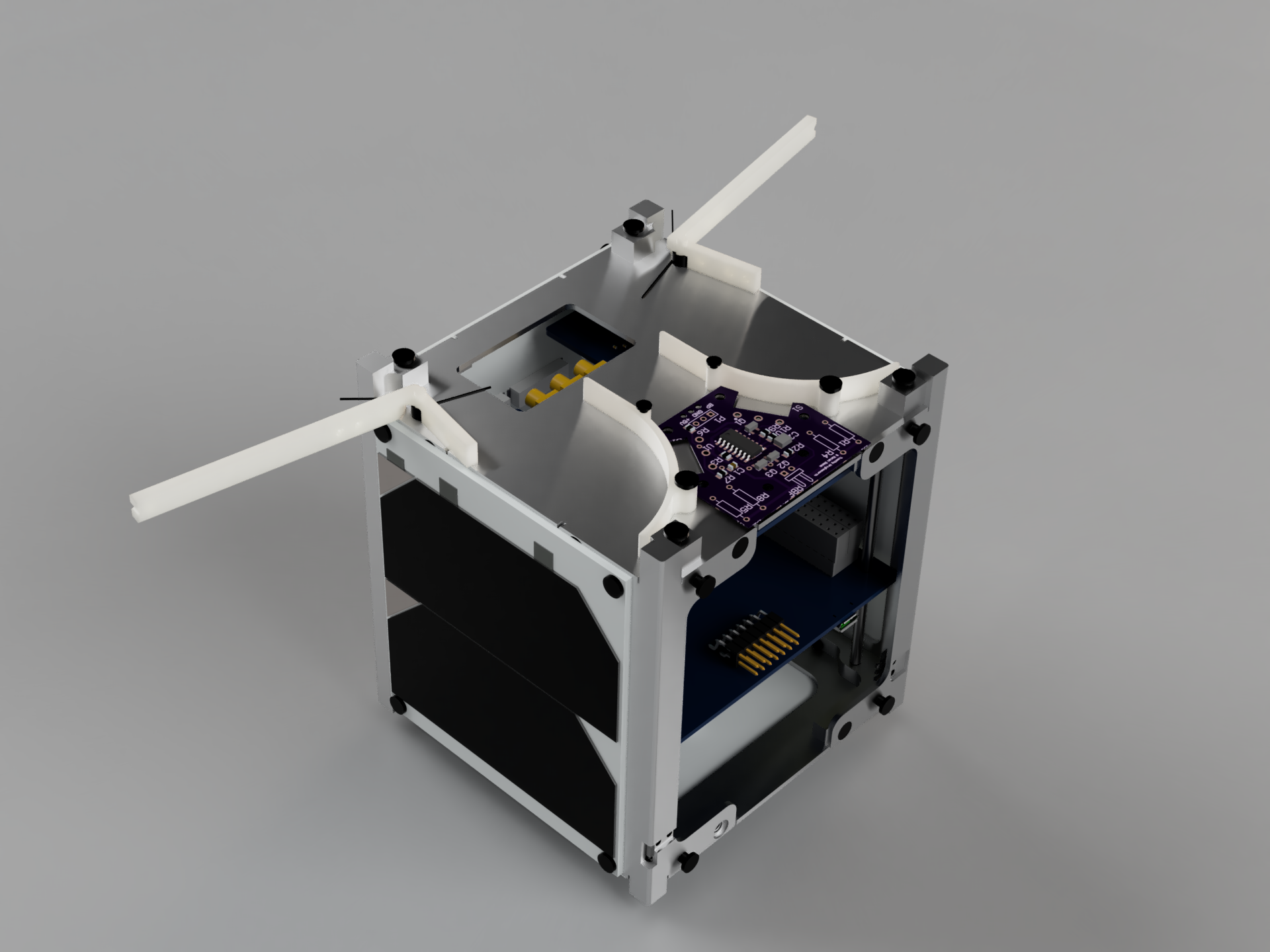


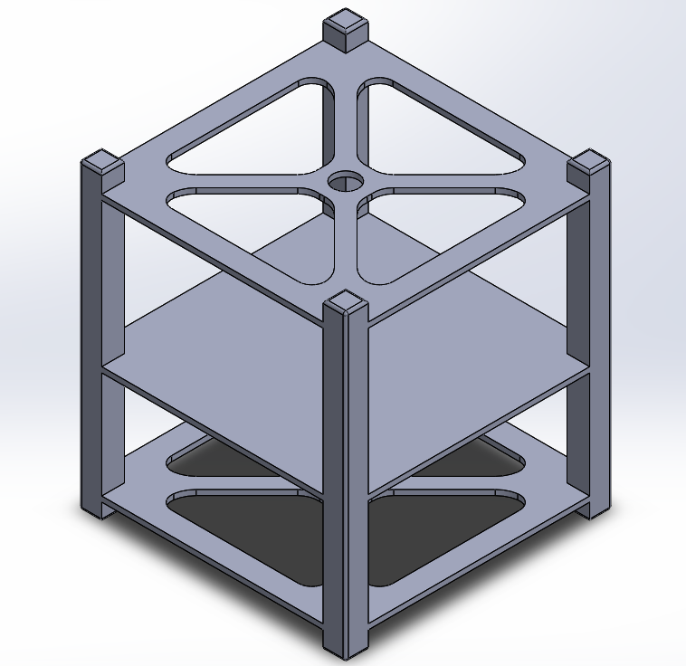
ALEASAT Reaction Wheel Test Rig
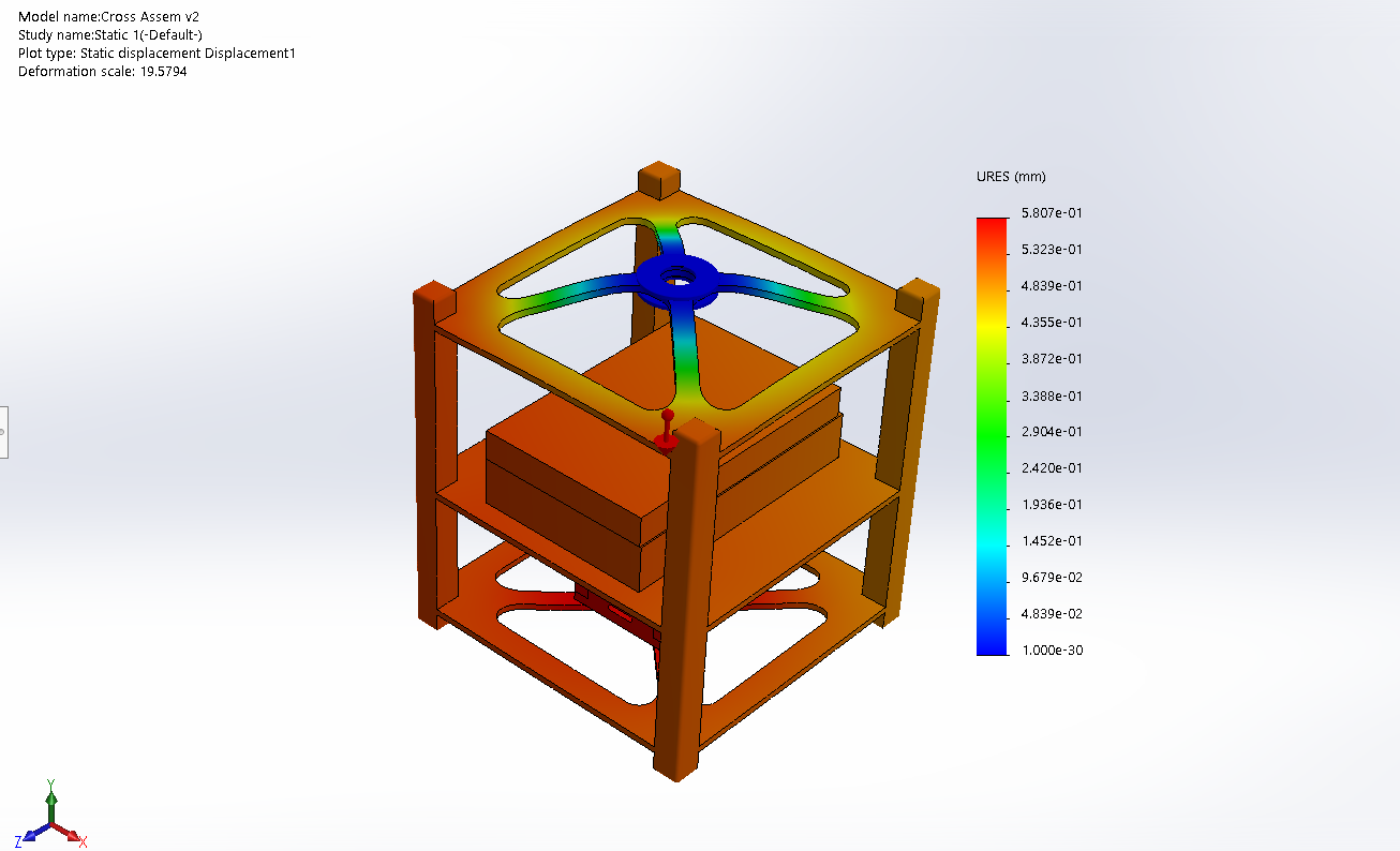
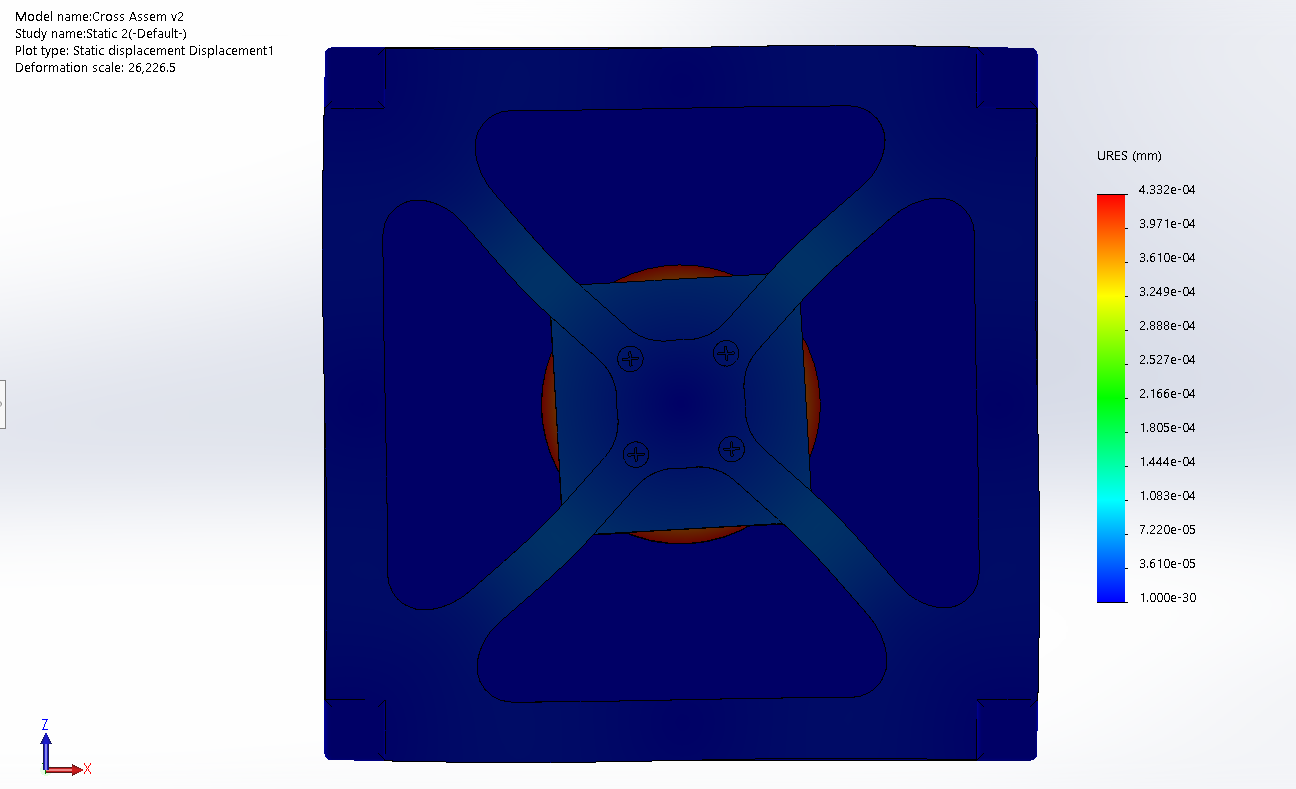
For my project-based class “Mechatronic Design II” I worked with a small team on a test rig for the custom reaction wheel that I helped design. Spacecraft require methods of automatically determining and controlling their orientation in three-dimensional space. Reaction wheels are commonly used to control orientation, with one wheel able to generate torque for one axis. In the absence of free-fall, this project aimed to gauge effectiveness in one plane, which will indicate the feasibility of scaling the design to multiple dimensions. To be useful, the final design must autonomously control a single axis, and the mechanical design must emulate the functionality of a flight-ready CubeSat to the best ability that the 3D printed design can handle. Three designs were created with analytical calculations, and simulated models are used to determine failure and structural characteristics. Once complete, the results were discussed and evaluated to determine the best design from the three proposals. The final decision was the cross structure, which was able to maintain structural integrity under all simulated and calculated loads and meet the other design requirements well.
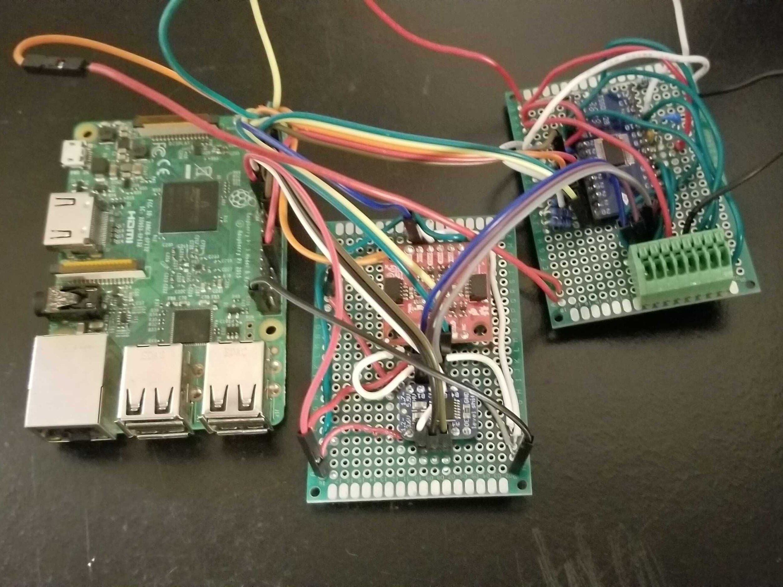
The electronics required for the project were based around the motor and flywheel previously designed and selected. The schematic was designed to use through-hole components on a proto-board so they can be easily reworked. The microcontroller chosen was the raspberry pi for its built-in wifi capabilities and its integration with MATLAB and Simulink, eliminating cross-compiling. The power source for the raspberry pi was a portable battery selected to provide enough current to the system and enable all physical tethering from a computer to be removed. Although the design was intended to be easily reworkable, the many passive components required to drive the H-bridge made the electronics challenging to work with and needed multiple protoboards.
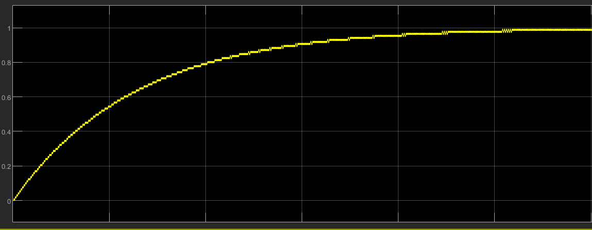
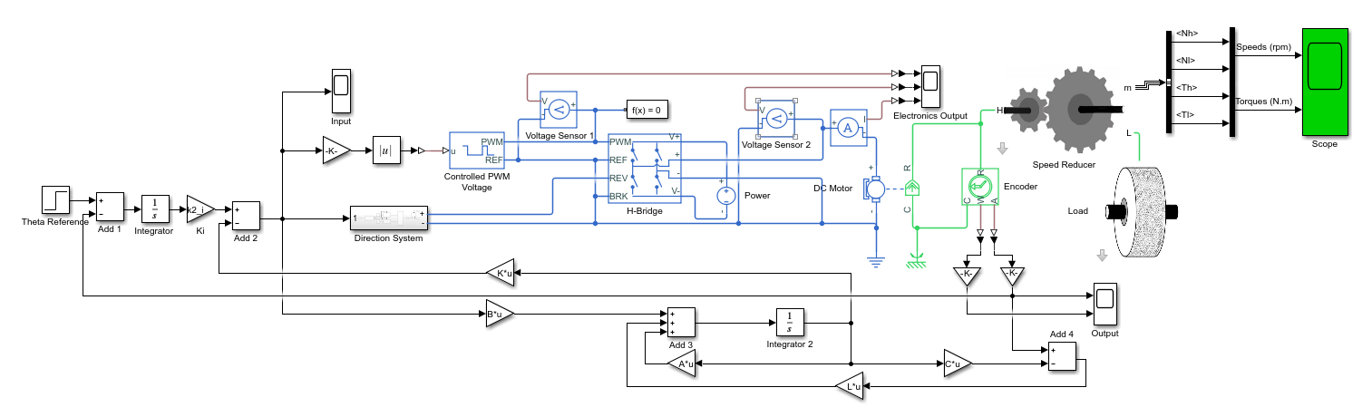
Both the brushless DC motor planned for the flight system and a simpler brushed DC motor were analyzed. The controller design and analysis for the system include PID control and a state-space (modern) control design. The input to the system is a PWM signal generated by a Raspberry Pi as the microcontroller; the output is the angular position of the satellite body. Based on the requirements derived by the SFU Satellite Design Team, the required settling time was less than 240 seconds, and overshoot was less than 1%. Based on the requirements, a root locus pole placement approach was used, and the necessary gains were calculated for the controller. After simulating the controller in continuous time, a discretized controller was implemented and loaded onto the raspberry pi, which reads the sensors in real-time and calculates the necessary PWM signal. Given the debugging still required in the electrical circuit, the discretized controller was not tested within this project’s timeline and is still a work in progress.


The canadian Satellite Design Challenge 5 (2018-2020)

Our first (left) and second magnetorquer prototypes
Our team was previously designing a CubeSat for the latest iteration of the CSDC. This development has now been shifted into ALEASAT. For CSDC 5 I primarily continued my work from CSDC 4 by working on ADCS. The satellite was to have an earth imaging camera as its primary payload which meant that the development of an active control system was required. Based on the missions pointing requirements we required the use of both reaction wheels (for precision and speed) and magnetorquers (for momentum dumping and detumbling). For determination, we were using a more advanced and improved version of our previous attitude determination system. In addition to the use of coarse sun sensors, we implemented a 9-DOF IMU sensor. Since the hardware for this was largely done, and only had to implement with the new system, most of the time was spent on the software side of determination and on the control.

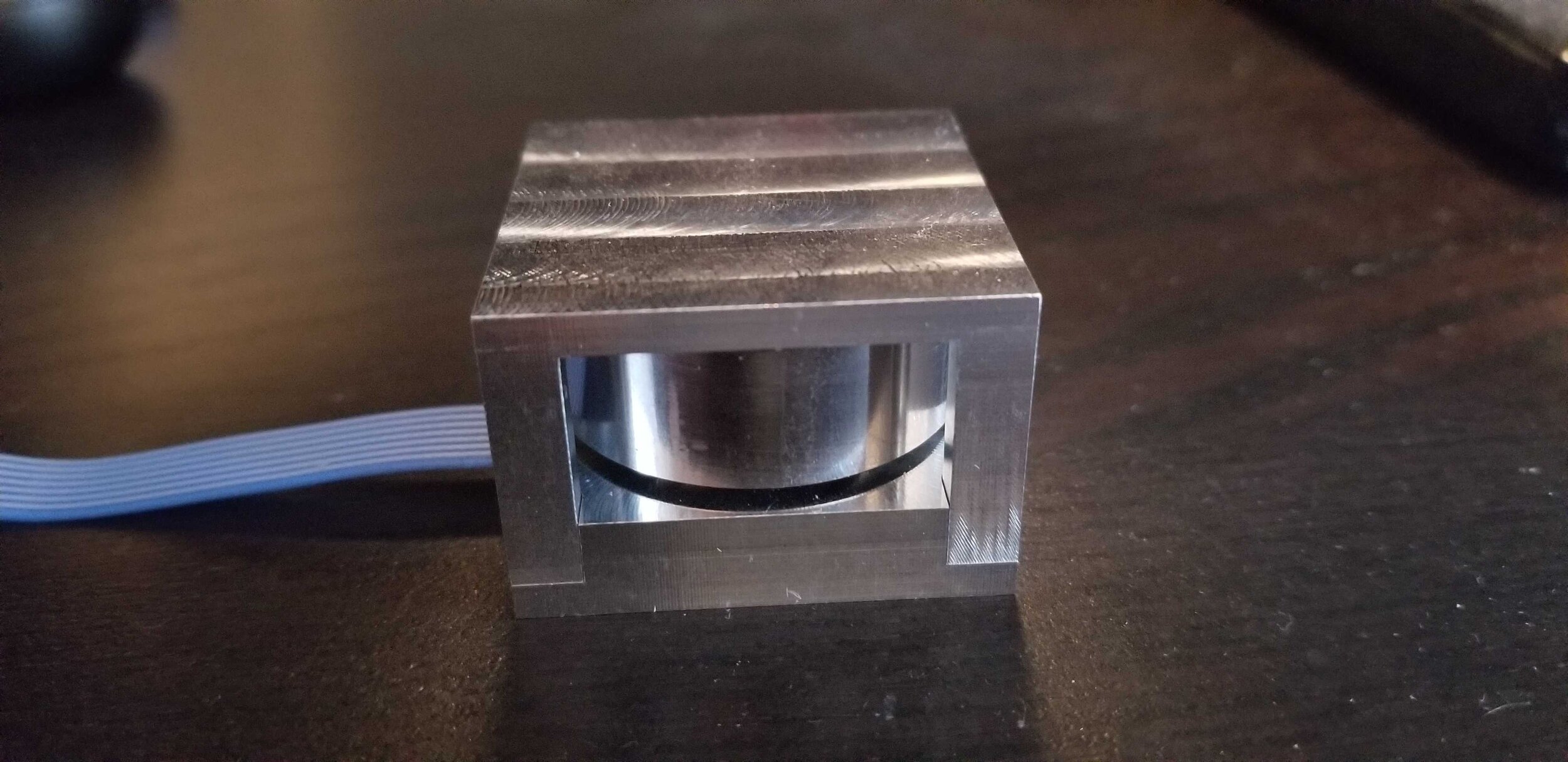
Our reaction wheel prototype: Steel flywheel in a temporary 3D printed housing for fit checks
We created an optimization algorithm to select our magnetorquers material and dimensions. Using a custom coiling machine, we have manufactured our first two prototypes. We managed to refine the process and improved the performance with our second prototype. We also developed another optimization algorithm to make final selections for our reaction wheel design. We created our first prototype reaction wheel which is now going to be used on ALEASAT.
Testing attitude control systems is itself a large task since we must simulate the freedom of movement in space. We had initial designs for an air bearing test rig. The whole system was to be managed by a TMS570 MCU which would take all the data from our sensors and from the primary computer (another TMS570) and then control our magnetorquers and reaction wheels accordingly. We will also be implementing the GPS system developed for the previous CSDC into this new design.
The canadian Satellite Design Challenge 4 (2016-2018)

First iteration of our CubeSat for the Canadian Satellite Design Challenge, without solar panels or endplates attached.
The Canadian Satellite Design Challenge (CSDC) is a Canada-wide competition for teams of university students (undergraduate and graduate) to design and build a small satellite. The satellites undergo full launch and space environmental qualification testing, with the goal of launching the winning satellite into orbit in order to conduct scientific research.
The CSDC lasts two years, our team’s first competition ended in June 2018. We completed a 3U CubeSat designed to do radio calibration for the Canadian Hydrogen Intensity Mapping Experiment (CHIME). I attended the final testing and evaluation in Ottawa at the Canadian Space Agency's David Florida Laboratory where we learned of proper cleanroom procedures and vibration testing methods. Previously the satellite had also undergone radiation testing at TRIUMF, Canada's national particle accelerator center. Although we did not win the competition, we were the only first-year team with a functioning system.
My work on this project was on the GPS, ADCS, and some structural components. One of my first tasks on the team was in researching GPS systems to eventually select our GPS. We purchased a Novatel OEM 719 Multi-Frequency GNSS Receiver which is common for CubeSats. We tested and configured the GPS using an Arduino and a DC power supply to achieve the strict power requirements instead of the $1000+ development kit which saved us significant amounts of money. The GPS was later attached to a PCB and connected via a coaxial cable to a patch antenna on the endplate of the satellite for receiving GPS data. The data was then sent to our on-board computer before being transmitted.

Hand placed and soldered components on our Y-axis exterior PCB panel
The attitude control system for our satellite was a passive permanent magnet and hysteresis rods used to align with the earth’s magnetic field. This system was sufficient for our payload which only needed the Z-axis to be pointed roughly towards the earth. However, to further our understanding of ADCS we designed an attitude determination system which was not technically required for this prototype satellite.
Our system used 16 coarse sun sensors to detect the location of the sun and determine the satellite’s orientation in space. We did a series of tests to characterize the behavior of our sensors. Since the sun sensors outputted a maximum of 1.6 mA when under direct sunlight (1367 W/m^2) we designed a circuit to amplify this maximum to correspond to 3.3 V. Each of the 4 long panels (X/Y-Axis) contained 3 sensors, each going to an op-amp and then to an internal panel connector board. The 2 panels on the top and bottom (Z-Axis) contained 2 sensors. The on-board computer collects the data by cycling through 4 multiplexers each then connected to 3-5 sensors.

Circuit schematic for a single coarse sun sensor and op-amp with LPF
Two of the multiplexers were attached to only a single X/Y panel (3 sensors) and two were attached to an X/Y panel (3 sensors) that was further attached via ribbon cable to a Z panel (2 sensors). All 6 of the exterior panel PCB's and the interior panel connector board were partially designed and assembled by our ADCS team. The assembly required careful application of solder paste and hand placement of various components.
In addition to this work on the ADCS team, I also helped with some structural components. I designed and 3D printed components for prototyping a mounting mechanism for the remove before flight system which could connect directly to a PCB. Using a milling machine, I helped to manufacture small aluminum components for assembling the CubeSat structure. I also worked on rapid prototyping, assembly, and revision for the exterior aluminum structure for testing.
The Canadian CubeSat Project - ORCASAT
The Canadian CubeSat Project (CCP) was announced in April 2017. The CCP is providing professors in post-secondary institutions with an opportunity to engage their students in a real space mission. Through this national initiative, winning teams of professors and students are offered the unique opportunity to design and build their own CubeSat.
I attended a meeting in October of 2017 with students and professors at Uvic and SFU to help organize a collaboration for the CCP. Our team at SFU joined with UBC and UVic for our proposal submission and we received a $200,000 grant from the CSA and a guaranteed launch. Our three universities will be collaborating to design, test, and build our satellite. The payload for our satellite is UVic's optical telescope calibration system.
In addition to working on ADCS, I helped with the ground station at UBC via the Spacecraft Systems Engineering course which I audited. I helped to manage the software development and integration for that system and worked on Python scripts for demodulation. The class project also had us develop a 1-day Spacecraft Systems Engineering course which we could present to members of the SFU, UBC, and UVic teams.

High-altitude balloon Project

Our balloon team doing final testing on campus before heading to northern BC for launch.
At the same time that I joined the team in September 2017, a number of new first years were started on a simpler balloon project as an introduction to the team. Although I was focused on the satellite, I also helped the balloon team. I served largely as a mentor and bridge with the rest of the team. The mission was to collect climate data in the upper atmosphere of BC using a series of sensors all controlled with an Arduino Mega. I helped the other students with the part selection, programming, and assembly. The onboard sensors which included temperature sensors, pressure sensors, and a GPS were all connected using breakout boards and breadboards. The GPS data was sent over the RF system to a follow car with a Yagi Antenna. The balloon was successfully launched in September 2018. The balloon project team members have now transitioned on to the main team working on the next CSDC for 2018-2020.
Gallery

Presenting a poster at the 33rd annual Small Satellite Conference at Utah State University

The first meeting of SFU and UVic to discuss the ORCASAT project

An SFUSAT weekend work session in one of our labs

Waiting to demonstrate our CubeSat’s antenna deployment system to CSDC judges at the Canadian Space Agencies David Florida Lab