


Our first team photo with 24 members, we have have since increased in size to around 50 members

Our first rocket which is designed to launch to 10,000 feet in the next few months
I founded SFU Rocketry in March 2018 and was elected as the club’s president. After serving as president for nearly 2 years I have stepped down and am now serving as a general advisor and systems engineer. As the president, I organized and ran general meetings, assigned tasks to other leads, and coordinated with competition organizers. Most of the additional administrative work was handled by our admin team and I focused on overseeing and guiding the design of the rocket. I managed the overall systems engineering of both of our 2 rockets in development at the time, but my primary contributions were to the avionics and propulsion systems.
The team is planning to launch a solid propulsion rocket at the Spaceport America cup in June 2020 and at the Launch Canada competition in August 2020. Our team is also working on a long-term project to design and launch a liquid propellant rocket. We plan to test-fire our liquid engine in late 2020. As part of this, I participated in a rocketry safety training session with instructors from NASA, Purdue, CSU, Boeing, and Pratt & Whitney. The session was over 12 hours and detailed safe design, operating procedures, team training, as well as the propellant, cryogenics, chemical, electrical, and pyrotechnics safety. I also completed an additional 12 hours of NASA LOX (liquid oxygen) training.
Website: www.sfurocketry.com
GitLab: www.gitlab.com/sfurocketry
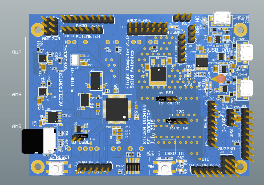
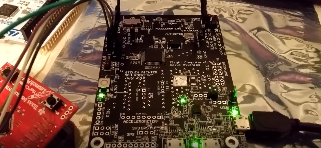
Avionics

Simple block diagram of the primary systems on our two solid propellant rocket avionics boards and how they communicate
I previously lead the avionics team for a large portion of my time as President and after finalizing the overall architecture we finished with our first two board designs. We were designing a system that will eventually work for both rockets currently in development with a focus on the first two boards which were needed for the solid rocket. The entire system was designed with safety and redundancy in mind. The solid propellant rocket will use 2 custom PCBs for control. The first is the primary computing system which will read from all of our sensors as well as control our recovery system. The second is the power board which also contains our remove before flight safety system. In future versions, we will be designing our own RF board. With our next rocket, we will also have a propulsion sensing and control board and our reaction control system board.
The MCU we are using is the TM4C123GH6PM, a popular device made by TI. The first two boards have been designed and manufactured and are now in the testing phase as we continue to improve our custom firmware. For our liquid propellant rocket, we are planning to use the Novatel OEM719 GPS which I have previously worked with on the SFU Satellite Design Team. In addition to the on-board systems, I am also working with the team to develop a ground station app to run off a laptop.
Reaction Control System (Cold Gas Thrusters)
My final project for MSE 450 Real-Time and Embedded Systems was a prototype Reaction Control System. For the project, we implemented a system to maintain 1-DOF control of a 4-inch diameter rocket. After completion of the project, the team is moving forward to develop a full 3 axis control system for the team’s sounding rockets.

Circuit design with only one valve shown which is connected to an optoisolator
The initial 1-DOF Reaction Control System uses pressurized air to balance a stand-in rocket body. The rocket’s body is free to rotate on a dowel and bearing and is naturally unstable. The system controlled by an STM32 Nucleo MCU balances by collecting and filtering data from an IMU and actuating two normally closed solenoid valves to release the air. The IMU data goes through a complementary filter which applies a low pass filter to the accelerometer and a high pass filter to the gyroscope. A hysteresis controller is used to actuate the two valves based on this data and control the orientation of the rocket body. The final system was capable of balancing for around 20 seconds before our compressor pressure dropped too low to maintain stability. In addition to passively balancing, the system is also capable of rebalancing after pushing the body in either direction. The next step will be to implement a more advanced PID controller and increase it to 2-DOF.

A simple piping and instrumentation diagram of our 1-DOF system
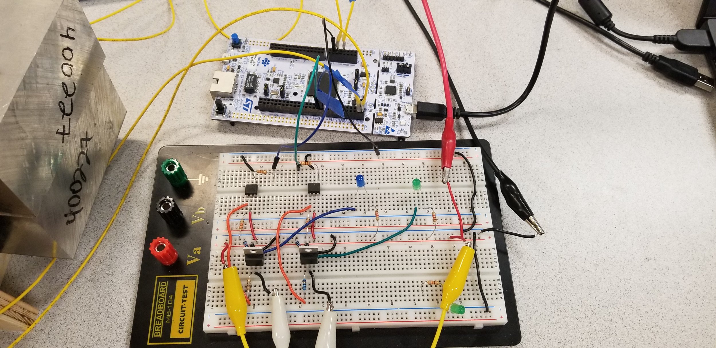
Our STM32 Nucleo board and circuit prototype

1-DOF reaction control system test stand complete with Electron logo and remove before flight tag
Propulsion

Our engine prototype design 3D printed in PLA for demonstration purposes
I also worked with the propulsion team on the system architecture and to ensure the proper integration of the avionics and propulsion systems. I did a significant amount of independent research in propulsion systems including listening to online lectures and reading books such as “Ignition!” and “Rocket Propulsion Elements.” I used this knowledge to teach members the fundamentals of rocket propulsion from the club’s inception and to help guide our engine’s design process.
When we first began working on liquid rocket engines myself and our propulsion lead researched and planned the crucial high-level parts of our engine design. This included research into propellants, plumbing & instrumentation diagrams, rocket power cycles, and various other systems. We narrowed down and selected our options based on our mission requirements.
Our engine is a bi-propellant engine using LOX and RP-1. It uses an electric pump-fed cycle to reduce the complexity of the system while still maintaining the required efficiency and mass requirements to reach space. The avionics team will be taking on a portion of the engine design work including working on the selection, integration, control, and design of the electric motor and battery system used to drive our custom centrifugal pump design. The pumps will be driven by electric brushless DC NeuMotors powered by lithium-ion battery packs. Each pump will have its own motor and motor controller which will need to be actively cooled. A pintle injector will be used for propellant mixing and vaporization due to its manufacturing simplicity. The combustion chamber will be 3D printed and use RP-1 for regenerative cooling.
Ball Valve Actuator

Prototype ball valve actuator
For my final project in the course “Computational Methods for Engineers“ I worked on the design of a ball valve actuator for the main fuel line of our liquid engine. The system uses a 4-bar linkage to increase the output torque of a servomotor. This will allow us to use a smaller, lighter, and cheaper servomotor. The linkage also allows the motor to be mounted parallel to the valve and not in direct contact. Me and two other students designed a linkage using MATLAB optimization techniques. The design was modeled in SolidWorks and 3D printed, however, we found that the design was not ideal due to the peak in torque required at certain angles. A second design is now in the works to limit or remove these peak torque input values.
Gallery


Our recovery deployment and descent profile

Our liquid propellant engine piping and instrumentation diagram

Meeting with members of the Portland State Aerospace Society to discuss our rocket engine designs

Me talking to various members of government about SFU Rocketry